First, Show That It Can Be Done
In Chapter 2, we established the physical and mathematical foundations of our manipulation cell: the multi-body kinematics of the UR5e arm, the inverse kinematic branches, and the three-tiered control hierarchy bridging high-level commands with motor dynamics.
Starting in Chapter 4, our goal is to train deep reinforcement learning policies that discover manipulation behaviors autonomously from environmental reward signals.
However, before launching multi-day training runs or hyperparameter sweeps, a fundamental engineering question must be answered:
Can the simulated robot perform this task at all, using only the action space and control constraints provided to the policy?
The 0% Dilemma
Suppose you initiate reinforcement learning training, and after 48 hours and 10 million simulation steps, the policy still achieves a 0% success rate. Two completely different failure modes produce the exact same outcome:
| Failure Mode | Underlying Root Cause | Correct Engineering Action |
|---|---|---|
| Learning Failure | The task is physically solvable, but the RL exploration mechanism, reward formulation, or network architecture failed to discover the path. | Refine reward shaping, adjust entropy regularization, tune learning rates, or train longer. |
| Environment Impossibility | The task is physically or computationally impossible due to a kinematic reach limit, rate clamp saturation, collision mesh snag, or bugged success detector. | Fix the physics, kinematics, or reward checker. No learning algorithm, no matter how advanced, can ever succeed. |
The second failure mode is insidious because engineers instinctively blame the machine learning model. They spend weeks switching algorithms (PPO SAC TD3), adding layers, or tuning entropy temperatures, completely unaware that the robot is physically incapable of completing the trajectory under the simulator's constraints.
To eliminate this ambiguity, we never begin with reinforcement learning. Instead, we construct an explicit, hand-written program that executes the task through the exact policy action interface: the Waypoint Expert.
In this chapter, our hand-written expert achieves 50 out of 50 successes (100%) across our standard evaluation scenes. In the process of achieving this benchmark, it exposed three critical simulation bugs that would have completely derailed any learning algorithm.
3.1 How a Manipulation Task Can Be Impossible
Before verifying feasibility, it is vital to understand the failure modes that can render a robotic manipulation task impossible. In a simulated cell, the arm appears to move freely, the table is large, and the cube is small. Yet subtle constraints can quietly prohibit success.
Figure 3.1 illustrates three distinct failure modes that occurred during the bring-up of our simulation environment.
Figure 3.1 Three ways a manipulation task can be physically or computationally impossible. All panels to scale. Panel 1: Kinematic over-extension (elbow at 18°) approaching singularity while carrying at 400 mm over the far bin. Panel 2: Orientation mismatch jamming diagonal cube clearance. Panel 3: Floating bin coordinate datum invalidating success detection.
1. Kinematic Singularities and Controller Clamping
In our waypoint expert, the robot carries grasped cubes across the cell at a transit clearance of above the tabletop. During an early experiment, we raised this transit altitude to across all 50 evaluation scenes.
The result: the middle-level controller refused 65 commands across 10 of the 50 attempts. Every refusal occurred exclusively when the hand moved above the far bin (the bin positioned farthest from the robot's pedestal).
As illustrated in Panel 1 of Figure 3.1, maintaining an altitude of over the far bin forces the UR5e arm to stretch into a nearly straight line. In Test Scene 9, the elbow flexes to an angle of only .
As we saw in Chapter 2, when a serial manipulator approaches an
extended kinematic singularity, the Jacobian matrix becomes
ill-conditioned: infinitesimal movements of the hand in Cartesian space
require massive, near-infinite angular velocities from the joints:
To prevent joint velocity jumps and actuator damage, the middle-level
controller (StreamerCore) clamps and rejects any command
that exceeds joint acceleration thresholds. On a physical industrial
robot, this triggers an emergency safety halt.
By dropping the transit plane to , the elbow remains bent at , keeping the arm deep inside its dextrous workspace ellipsoid where the controller executes every motion without rejection.
2. Gripper Orientation Constraints
In realistic industrial bin-picking, cubes do not land neatly aligned with Cartesian axes; they settle at arbitrary yaw angles ().
If the robot's action space lacks a degree of freedom to adjust the wrist tilt/yaw (or if an RL policy fails to rotate the gripper), the jaws descend square while the cube rests at an angle (Panel 2). A cube with an edge length of has a corner-to-corner diagonal dimension of: If the gripper jaws close onto the opposing corners rather than the parallel flat faces, the fingers either jam, deflect the object across the table, or establish an unstable, high-energy point contact that pops out upon lifting. The action space must explicitly support wrist rotation ().
3. Faulty Success Contract and Metric Drift
Panel 3 illustrates a purely computational failure mode: the robot executes the pick-and-place motion flawlessly, deposits the cube into the bin, and releases its grasp—yet the environment awards a reward of 0 and marks the episode as a failure.
If the success detector's geometric bounding box is misaligned, if vertical thresholds are calculated from the wrong structural datum, or if coordinate frames drift, the policy never receives positive reinforcement.
None of these three failure modes triggers a Python exception or crashes the physics engine. In all three cases, an RL agent would simply output zero reward indefinitely, leaving the practitioner with zero visibility into the true root cause.
3.2 Why Random Action Probes Prove Almost Nothing
A common heuristic when bringing up a new RL environment is to execute a random policy—sampling actions uniformly from the action space —to observe how the environment behaves.
We executed this random baseline across our 50 fixed evaluation scenes. Each episode was allocated a generous horizon of 800 steps ( at ). Table 3.1 summarizes the findings:
| Verification Criterion | Empirical Outcome | Engineering Diagnostic |
|---|---|---|
| Physics Stability | 0 Crashes / 0 NaN outputs | MuJoCo integrator and contact manifolds remain numerically stable. |
| Safety Violations | 262 Controller Refusals (in 30/50 runs) | High-frequency noise frequently triggers joint velocity ceiling trips. |
| Workspace Dispersion | Mean net displacement of | Hand wanders widely across the entire workspace. |
| Object Interaction | Accidental cube push in 13 runs; 2 balls knocked off table | Hand collides with clutter without coordination. |
| Grasp Establishment | 0 grasps established | Jaws never maintain closure during upward transit. |
| Task Success | 0 of 50 (0.0%) | Uninformative pass/fail result. |
Figure 3.2 Top-down projection of Test Scene 0 workspace. Left: Hand trajectory across ten attempts using uniform random actions (800 steps each). Right: Targeted trajectory executed by the deterministic waypoint expert.
As Figure 3.2 illustrates, a random policy executes a Brownian wander: it flails across the tabletop, occasionally knocking over cubes or launching clutter off the table.
However, solving pick-and-place requires executing an unbroken sequence of approximately 50 coherent, purposeful decisions:
- Hover directly over the cube.
- Align gripper angle with the cube's principal axes.
- Descend vertically along the table normal without colliding.
- Squeeze jaws until bilateral frictional lock is achieved.
- Maintain squeeze pressure while reversing vertical direction.
- Transit horizontally without striking bin walls.
- Lower into container footprint and release.
If the jaw command fluctuates randomly between (open) and (close) ten times every second, the probability of maintaining closure across 50 consecutive steps by pure chance is practically zero:
Therefore, a random test proves almost nothing. It confirms that the simulation does not crash, but it cannot differentiate between an impossible environment and a difficult learning task.
3.3 A Policy Written by Hand: The Waypoint Expert
Because random probing cannot establish feasibility, we engineered an
algorithmic baseline: the Waypoint Expert
(policies/expert/pick_place.py).
To ensure the test is mathematically valid and representative of what a neural network must achieve, the expert is bound by two strict architectural rules:
Rule 1: Exact Same Action Contract
The expert must interact with the environment exclusively through the exact same 5D normalized action vector emitted by an RL policy:
- Displacement Components (): Scaled such that requests a maximum translational increment of over the policy period.
- Wrist Yaw (): Scaled such that requests a rotation of .
- Jaw Opening (): Normalized position setpoint ( = fully open at ; = fully closed).
Every action emitted by the expert passes through the middle-level
controller (StreamerCore), respects the
rate limiter, and is converted into joint torques by the
PD loop. The expert is not permitted to teleport links, modify joint
variables directly, or bypass physical simulation.
Rule 2: Privileged Oracle Perception
While the expert's actuators are strictly constrained, its perception is granted ground-truth privileged access to the simulation state:
- Ground-truth 3D position of the cube .
- Ground-truth planar orientation (yaw angle ).
- Ground-truth 3D position of the target bin .
- Direct bilateral contact verification
(
grasp_verified = Truewhen both gripper pads exert sustained normal force against the cube).
Is this cheating? Yes—deliberately so. The purpose of Chapter 3 is not to determine whether a vision system can estimate object poses from noisy camera pixels (a topic addressed in Chapter 9). The purpose is to isolate the physical and kinematic controllability of the cell. If an oracle with perfect knowledge of the world cannot solve the task through the action space, a vision-based policy never will.
The Nine-Phase Finite State Machine
The expert decomposes the manipulation task into a 9-phase finite state machine (FSM), illustrated in Figure 3.3:
Figure 3.3 The nine-phase finite state machine (FSM) executed by the waypoint expert, shown from the side. Vertical clearances and transit heights are drawn to scale.
- Phase 1:
PREGRASP_OPEN— Set jaws to half-open (). Fully open jaws () risk striking neighboring objects during transit. - Phase 2:
APPROACH— Transit at altitude to above the cube; simultaneously align wrist yaw with the cube's orientation. - Phase 3:
DESCEND— Controlled vertical descent along table normal to grasp altitude datum. - Phase 4:
GRASP_CLOSE— Squeeze jaws until bilateral pad contact pressure is verified. - Phase 5:
LIFT— Retract vertically to clear surrounding table clutter. - Phase 6:
TRANSPORT— Traverse horizontally across table at safety plane until centered over target bin. - Phase 7:
PLACE_APPROACH— Descend to above bin rim. - Phase 8:
PLACE_DESCEND— Controlled descent to above bin floor. - Phase 9:
RELEASE_OPEN— Open jaws, release cube, verify containment.
The Proportional Deceleration Governor (P-Governor)
A critical engineering insight in waypoint following is managing deceleration. If the expert commands full displacement (, corresponding to ) right up until the target coordinate, the robot's physical inertia and actuator lag cause the hand to overshoot by several centimeters, requiring oscillation and correction.
To achieve smooth, critically damped arrivals at waypoints, the expert governs its commanded velocity proportionally to the remaining Cartesian distance:
# policies/expert/pick_place.py
delta = target_pos - current_hand_pos
distance = np.linalg.norm(delta)

# Command 1/5th of remaining distance per 100 ms step
cmd_step = delta / 5.0

# Normalize into policy action space [-1, 1], where 1.0 == 50 mm
action[:3] = np.clip(cmd_step / 0.050, -1.0, 1.0)- Far from target (): One-fifth of the distance exceeds the rate limiter, so the controller advances at the maximum safety ceiling ().
- Close to target (): The requested velocity decays smoothly to zero. The waypoint is considered reached when .
When we tested commanding full displacement versus this proportional deceleration rule across eight benchmark scenes, cumulative trajectory overshoot was slashed from down to !
Furthermore, during vertical descent toward the table (Phase 3), the governor enforces an extra ceiling of . At higher approach velocities, actuator lag caused the fingertips to ram into the tabletop before the controller could brake.
3.4 Fifty Out of Fifty: Empirical Validation and Edge Cases
With the waypoint expert implemented, we scored it across the standard 50 evaluation scenes. Video 3.1 showcases an execution in Test Scene 0 (the exact scene where the learned policy from Chapter 1 required 295 steps and three grasp attempts).
Video 3.1 Waypoint expert execution in Test Scene 0. Left: Overhead cell camera. Right: Wrist-mounted in-hand camera. Completes in 189 steps (18.9 s).
Unlike the exploratory policy, the expert moves directly along linear segments, executes a single decisive grasp closure, and deposits the cube in 189 steps ().
Figure 3.4 provides an interactive timeline scrubber of this rollout:
Figure 3.4 Interactive inspection of the expert execution. The horizontal progress strip segments the episode into the nine FSM phases. Drag the slider to observe synchronous telemetry and contact state.
Table 3.2 compiles the comprehensive benchmark statistics across all 50 test scenes:
| Performance Metric | Waypoint Expert (Oracle) | RL Benchmark (Chapter 7) |
|---|---|---|
| Success Rate | 50 of 50 (100.0%) | 47 of 50 (94.0%) |
| Controller Refusals | 0 | 4 |
| Mean Episode Length | () | () |
| Fastest Episode | ||
| Slowest Episode |
The Slowest Attempt: Clutter Collision in Test Scene 20
While 49 of the 50 episodes completed in under 220 steps, Test Scene 20 took a staggering 569 steps.
Investigating this outlier revealed an important physical interaction: jaw closure on the yellow cube took 350 steps (compared to an average of 15 steps in the other scenes).
Figure 3.5 breaks down the sequence using our high-resolution close-up diagnostic camera:
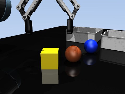
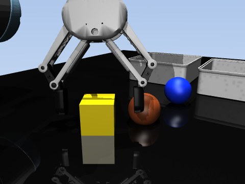
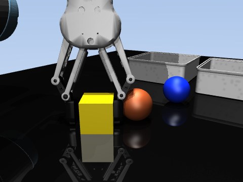
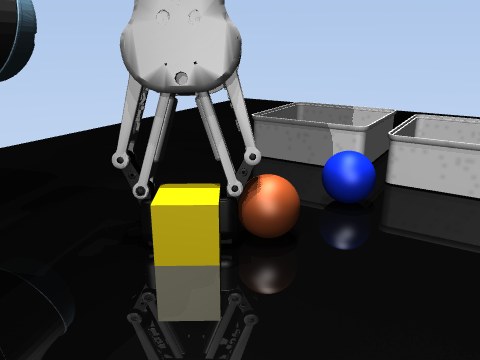
Figure 3.5 Multi-step clutter collision recovery in Test Scene 20 (close-up camera view). The right gripper finger lands on an adjacent ball, deflects laterally, and slowly re-converges to secure the yellow cube after 350 closure ticks.
Video 3.2 Close-up diagnostic camera recording of Test Scene 20 (steps 90 to 480).
- Step 100: The gripper descends with jaws half-open ( width). A brown clutter ball sits only from the edge of the target yellow cube.
- Step 115: Because the FSM does not actively scan for clutter on its descent path, the right jaw lands directly on top of the ball, exerting up to of downward normal force.
- Step 123: As the jaws command closure, the curved finger pad slips off the spherical surface of the ball. The resulting elastic reaction pushes the entire gripper laterally and downward, wedging the left pad firmly against the table.
- Step 466: The expert's grasp verification logic
continues polling
grasp_verified. Every 12 seconds, it micro-steps the closure command. Slowly, frictional slip allows the fingers to recenter until bilateral contact is finally achieved, permitting the lift to proceed.
This edge case demonstrates that while our waypoint expert possesses zero high-level scene reasoning, its requirement for true bilateral contact verification prevented it from dropping the object prematurely.
What 50/50 Proves vs. What It Does Not Prove
| What 100% Success Proves | What 100% Success Does NOT Prove |
|---|---|
| The action space is expressive enough to solve the task. | That the task can be solved from camera pixels alone. |
| The rate limiters () allow adequate travel speed. | That an RL policy will easily discover these trajectories. |
| The robot's kinematic reach covers all cube and bin placements. | That sim-to-real gap is zero without domain randomization. |
| The success detector and reward contracts are logically sound. | That blind policies can handle arbitrary clutter obstructions. |
Lesson Always build a hand-crafted deterministic expert before training an RL policy. If the expert achieves 100%, the physical action space is validated. If an RL agent subsequently fails to learn, the flaw lies in exploration, representation, or reward formulation—not in impossible mechanics.
3.5 Three Critical Bugs Uncovered by the Expert
Beyond validating kinematic reach, developing the waypoint expert yielded an immediate, high-value dividend: it uncovered three critical simulation bugs that would have poisoned reinforcement learning training.
Bug 1: The Floating Bin (Reference Frame Inversion)
During environment bring-up, we implemented randomized placement of the deposit bins ( jitter on the table). Immediately after enabling this randomization, the expert's success rate collapsed from 8/8 to 0/8.
Crucially, the expert still located, grasped, lifted, and transported the cube over the bin every single time—yet scored 0.
Inspection revealed a coordinate frame confusion:
- The compiled MuJoCo XML model specified the bin's vertical coordinate relative to its geometric midpoint ().
- The environment configuration YAML specified the bin's physical height by its upper rim ().
The randomization code erroneously read the rim height and assigned it directly to the model's geometric center. As a result, both bins were spawned floating in mid-air above the tabletop (Figure 3.6).
Figure 3.6 Bug 1 (The Floating Bin). Left: Correct placement (cube center rests at 28 mm, well below the 60 mm rim threshold). Right: Coordinate datum bug placing the bin 32 mm above tabletop (cube center ends at 62 mm, failing the detector by 2 mm).
When the expert dropped the cube into the raised bin, the cube came to rest on the container floor at . The success detector evaluates:
- Horizontal containment: PASSED
- Vertical containment: FAILED ()
The attempt failed by exactly !
The Fix: We refactored all spatial randomization
logic in envs/randomize.py to operate strictly on relative
displacements
()
relative to compiled neutral positions, rather than overwriting absolute
coordinate values.
Bug 2: Premature Optimization and the Gripper Bottleneck
In early builds, completing an episode took 529 steps (). Assuming the arm was simply too slow, we quadrupled the controller's translational speed limit ().
The result was catastrophic: success dropped from 8/8 to 1/4, and episode duration actually increased to 580 steps! The fast arm repeatedly overshot waypoints and hunted back and forth.
We then profiled where steps were actually being spent in the episode (Figure 3.7):
Figure 3.7 Bug 2 (The Gripper Bottleneck). Step allocation breakdown before and after grasp datum correction. Top: Sub-surface grasp datum caused jaws to grind against tabletop, wasting 503 of 724 steps (69%). Bottom: Corrected grasp datum reduced closure time to 15 steps.
The arm was not the bottleneck at all! In an un-optimized episode of 724 steps, 503 steps (69.5%) were spent entirely in Phase 4 (closing the jaws).
The root cause was a grasp altitude datum miscalibration: the expert was commanding the gripper too deep, causing the rubberized fingertips to drag against the tabletop while closing. Friction against the table slowed finger convergence to a crawl.
The Fix: Shifting the grasp altitude datum upward by allowed the fingers to close freely in air around the cube's upper perimeter. Jaw closure dropped from 503 steps down to 15 steps!
Lesson Never optimize execution speed based on intuition. Profile step distribution across phases first.
Bug 3: The Priority Inversion in MuJoCo Contact Dynamics
Later in the project, we began developing domain randomization for friction (varying cube surface lubricity). To verify the feature, we decreased cube sliding friction by a factor of 10.
When we evaluated the expert, the trajectory did not change by a single millimeter. Down to machine floating-point precision, joint angles and step counts remained completely identical.
The cause lay in MuJoCo's internal contact resolution rules: When two
geoms touch, MuJoCo must resolve the effective friction coefficient
.
MuJoCo determines this by checking the priority attribute
of the touching geoms. The geom with the higher priority dictates the
contact properties.
In the robot cell definition, the gripper pads had been assigned
priority="1", while the objects had
priority="0". Consequently, whenever the fingers held a
cube, MuJoCo strictly evaluated the friction of the gripper
pads, completely ignoring the randomized friction of the
cube!
The Fix: We explicitly configured MuJoCo geom
contact pairs
(<contact><pair ... /></contact>) to
compute combined friction using geometric harmonic means rather than
unilateral pad override. Immediately, slippery cubes began slipping
under heavy acceleration, allowing domain randomization to function as
intended.
3.6 The Expert as a Regression Test Harness
The value of the waypoint expert extends far beyond initial
verification: it serves as a permanent regression test
harness in our test suite
(tests/policies/test_expert.py).
Whenever we introduce a new physics feature, compile a new MuJoCo model, or refactor the environment pipeline, we run the expert across domain randomization sweeps:
| Environment Perturbation Tested | Expert Success Rate | Verification Conclusion |
|---|---|---|
| Object & Bin Scaling () | 16 of 16 (100%) | Model pool sizes remain graspable. |
| Dynamics Randomization (Mass , Gain ) | 16 of 16 (100%) | PD controller maintains tracking stability. |
| Sensor Perturbation (Camera Jitter, Joint Noise) | 16 of 16 (100%) | Oracle unaffected (proves control robustness). |
| Workspace Shuffling (Free placement, 1 vs 2 bins) | 24 of 24 (100%) | Table clearance planes safe everywhere. |
| Compound Domain Randomization (All above simultaneously) | 24 of 24 (100%) | Zero controller refusals. |
| Actuator Latency Injection () | 16 of 16 (100%) | P-governor smoothly absorbs minor delay. |
| Actuator Latency Injection () | 7 of 16 (43.8%) | Failure boundary reached. |
Notice the sharp boundary in the final row: while the expert tolerates a control delay, increasing latency to causes success to collapse to 43.8%. The phase lag introduced by the delay causes the P-governor to overshoot targets and fail grasp alignment. This empirical finding sets our hard sim-to-real latency budget: the physical robot pipeline must maintain an end-to-end latency below .
Looking Ahead to Chapter 4
We have established beyond doubt that our manipulation cell is physically, geometrically, and computationally sound. A sequence of 5D Cartesian commands can reliably pick and place any cube under realistic actuator constraints.
However, our waypoint expert relied entirely on human intelligence: an engineer hand-coded every waypoint, every threshold, and every transition rule, backed by privileged oracle knowledge.
In Chapter 4, we remove the human programmer. Can an autonomous artificial intelligence agent discover these exact manipulation strategies from scratch, guided by nothing more than a scalar numerical score?