Visual Glossary of Robotics & Manipulation Terms
Robotics and physics simulation combine mechanical engineering, multivariable calculus, and real-time control. For non-native English speakers—and engineers entering robotics from software backgrounds—words like pedestal, tilt, umbilical cabling, and flange can sound poetic or ambiguous.
This appendix provides a comprehensive visual and linguistic reference for every specialized term used throughout this book, complete with CAD engineering diagrams, plain-English definitions, physical roles in our UR5e cell, and notes clarifying common linguistic confusions.
B.1 Mechanical & Structural Hardware
1. Pedestal (Mounting Base)
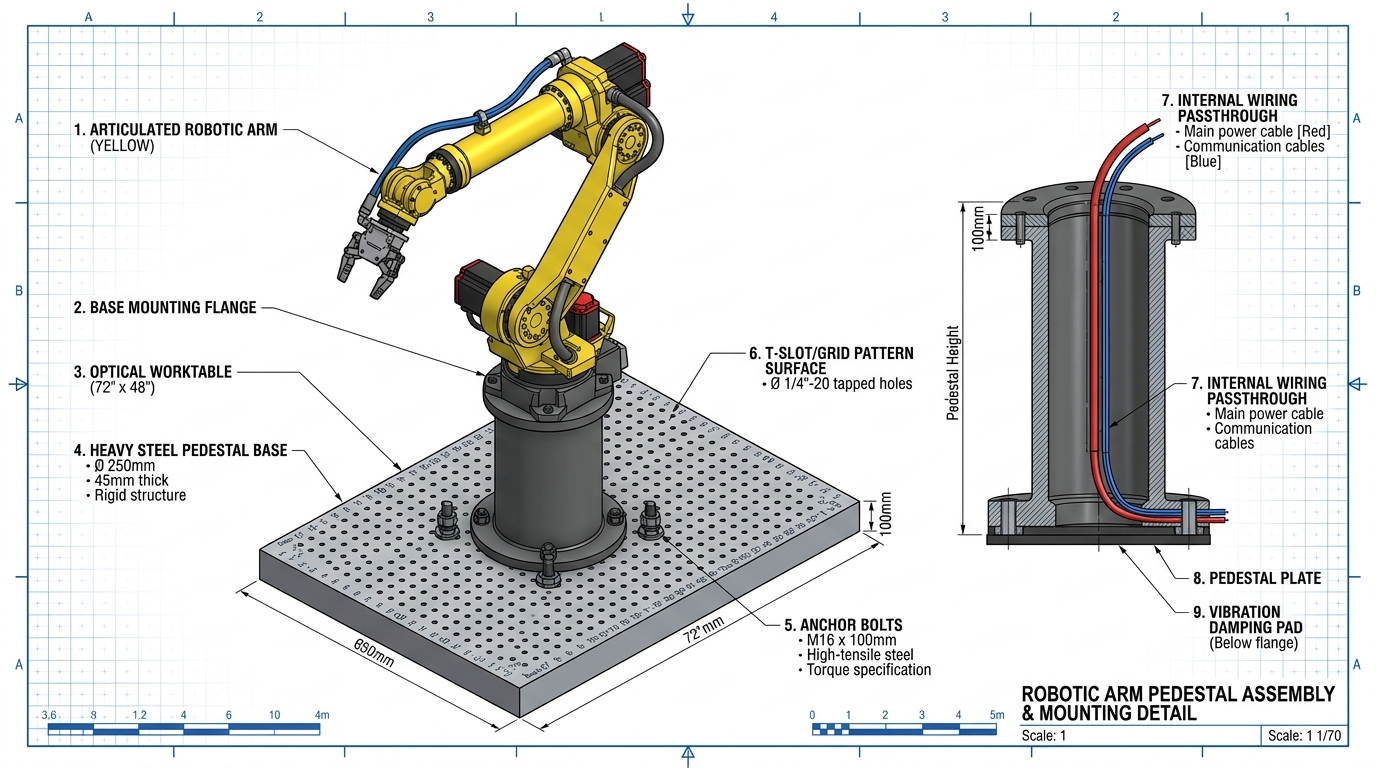
Figure B.1 Engineering breakdown of the robot pedestal assembly. The heavy cast-metal base elevates the arm above the optical worktable, withstands high dynamic motor torques, and routes internal cables through the table surface.
- Part of Speech: Noun
(
/ˈpɛd.ə.stəl/). - Plain English Definition: A heavy, rigid vertical mounting column, pillar, or stand that anchors an industrial machine firmly to the floor or workstation so it cannot wobble, bend, or tip over.
- In Our Manipulation Cell: The UR5e arm is securely bolted to a cylindrical steel pedestal fixed to the optical table. This pedestal provides vertical clearance so the shoulder link can rotate without colliding with tabletop equipment, while internal cutouts allow power and Ethernet cabling to pass cleanly underneath the table.
- Note for Non-Native English Speakers: In everyday conversational English, a "pedestal" often refers to an artistic stand for a marble statue or a vase (or the idiom "to put someone on a pedestal"). In mechanical engineering and robotics, it has zero artistic meaning: it is a heavy-duty structural steel base engineered to resist violent twisting forces (reaction torques) generated by fast-moving motors.
2. Tool Flange & End-Effector
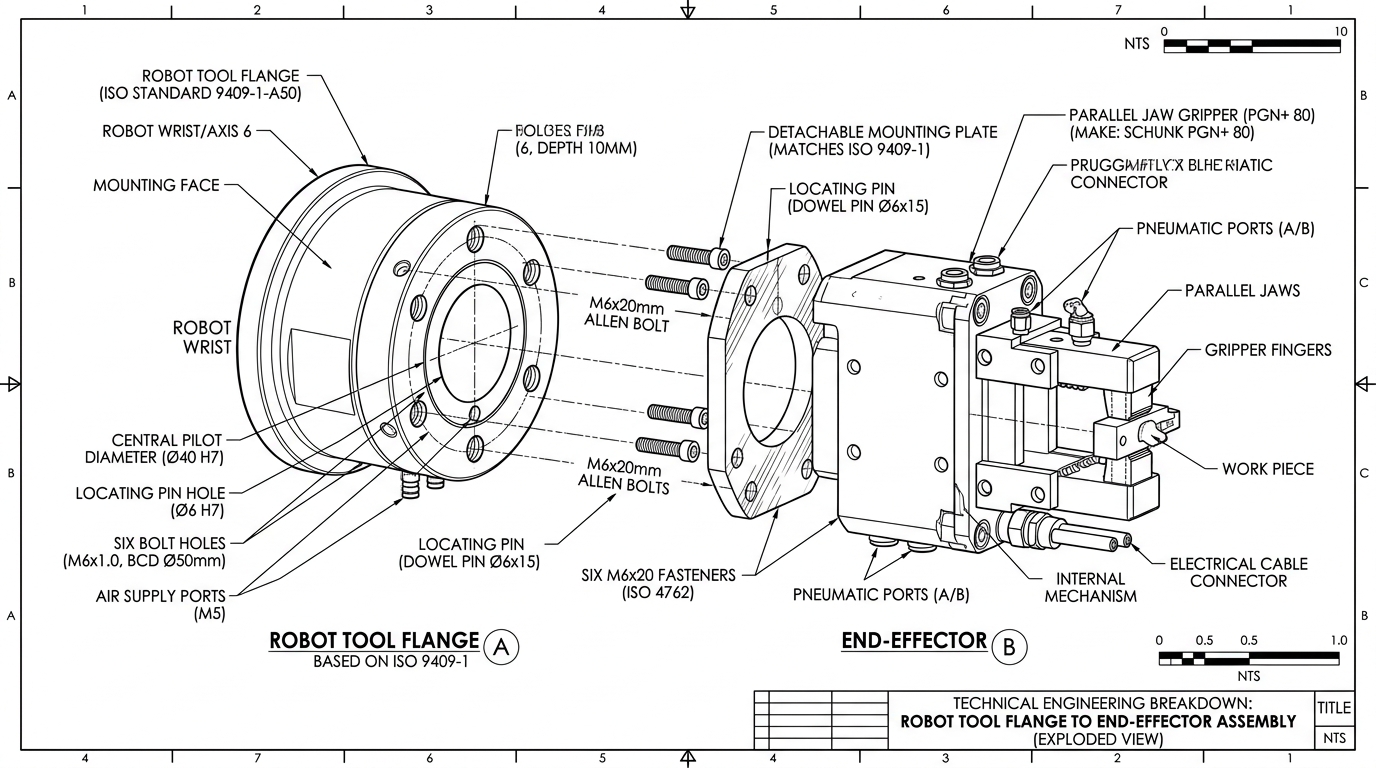
Figure B.2 Exploded assembly of the robot tool flange and end-effector. The standardized circular metal flange on Axis 6 provides precision bolt holes and dowel pin alignment for mounting the two-jaw gripper.
- Tool Flange (
/flændʒ/, Noun): The flat, circular metal mounting collar or rim at the very tip of the robot's arm (Wrist 3 / Axis 6). It follows an international standard (ISO 9409-1) with precision-machined threaded bolt holes and a central alignment pilot so tools can be mounted rigidly and repeatedly. - End-Effector (
/ˈɛnd ɪˌfɛk.tər/, Noun): Any specialized tool, gripper, or sensor mounted onto the tool flange that directly touches or acts upon objects in the physical world. In our cell, the end-effector is the OnRobot RG6 parallel-jaw gripper. In other factories, an end-effector could be a vacuum suction cup, a welding torch, a laser cutter, or a paint sprayer. - Note for Non-Native English Speakers:
- "Flange" sounds like strange jargon, but it simply means any protruding flat rim used for fastening parts together (pipes, train wheels, and robot wrists all have flanges).
- "End-Effector" combines end (tip of the arm) and effector (something that effects or causes an action).
3. Umbilical Cabling (Dress Pack)
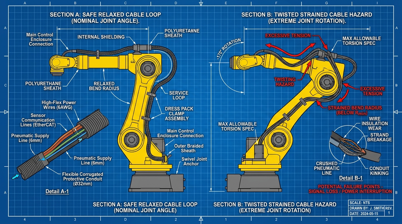
Figure B.3 Robotic arm umbilical cabling (dress pack). Left: Safe relaxed cable loops during nominal operation. Right: Cable twisting and strain hazard when joint configurations flip across kinematic branches.
- Part of Speech: Noun
(
/ʌmˈbɪl.ɪ.kəl ˈkeɪ.bəl.ɪŋ/). - Plain English Definition: A flexible protective bundle of electric power lines, high-speed communication wires, and pneumatic tubes routed through articulating joints to deliver power and data to the robot's moving wrist and gripper.
- In Our Manipulation Cell: The RG6 gripper, wrist camera, and joint encoders are connected to the central robot controller via a cable harness protected by flexible corrugated conduit. When the robot performs a "wrist flip" (), this cable bundle is severely twisted, which can pinch wires, degrade sensor signals, or cause wire fatigue and breakage.
- Note for Non-Native English Speakers: The term is borrowed from biology (the umbilical cord that feeds a baby in the womb) and astronautics (the cable tower connected to a rocket before launch). In industrial robotics, technicians also call this assembly the cable dress pack or cable harness.
B.2 Kinematics & Geometry
4. Tilt (Wrist Tilt vs. Pitch, Yaw, Roll)
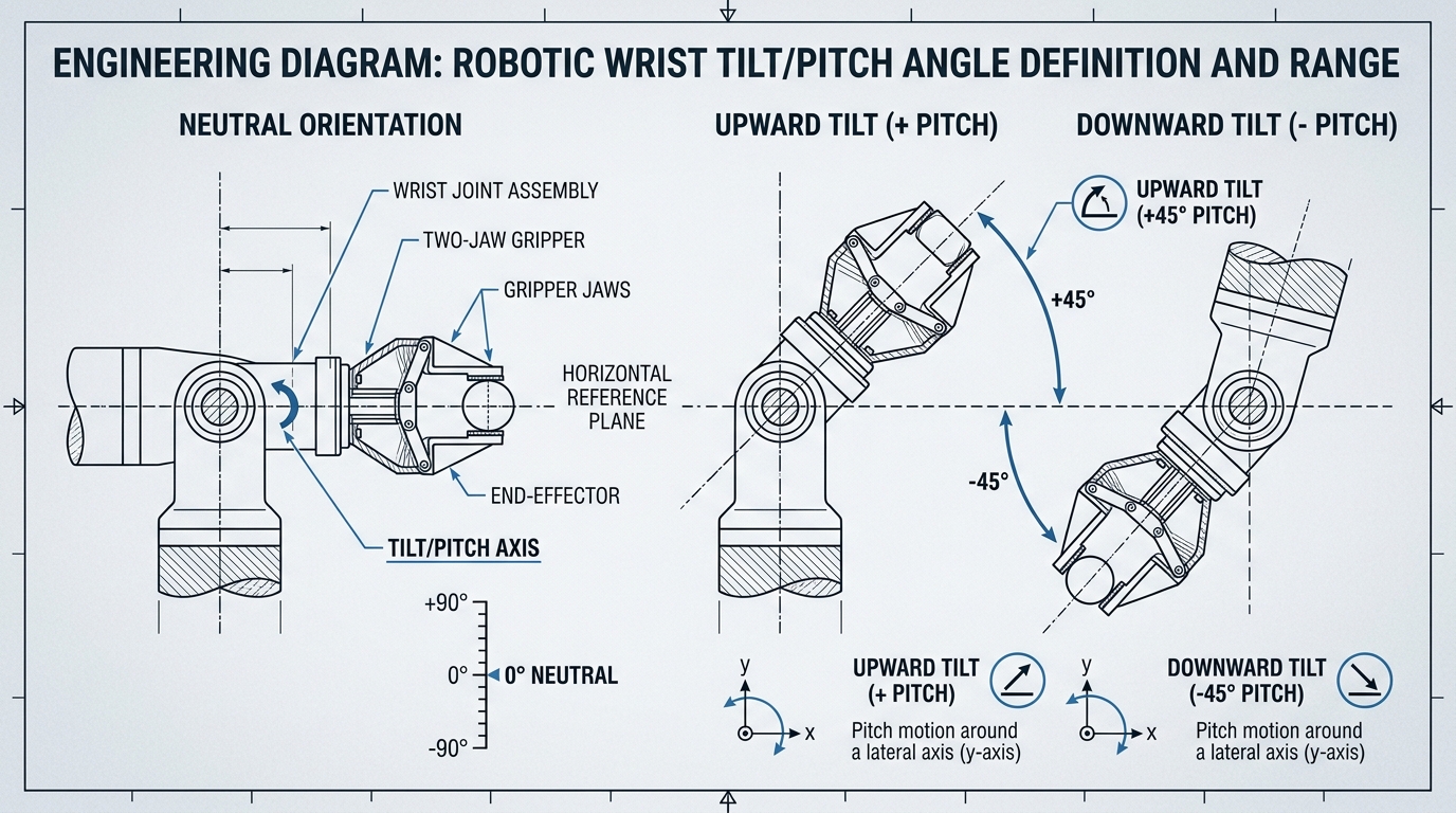
Figure B.4 Definition of robotic wrist tilt (pitch angle). Rotating Joint 5 angles the gripper jaws upward (+pitch) or downward (-pitch) relative to the horizontal table plane.
- Part of Speech: Verb & Noun
(
/tɪlt/). - Plain English Definition: To slope, slant, or angle away from a level horizontal or vertical line; leaning up or down.
- In Our Manipulation Cell: Wrist Joint 5 controls the tilt (pitch) of the gripper. In our standard grasping pose, the wrist is tilted down at so the fingers point straight at the table surface. In Section 2.3's inverse kinematics switchboard, inverting the wrist tilt from to points the wrist upward, triggering a flip in joints 4 and 6.
- Note for Non-Native English Speakers: In spatial
mechanics, 3D rotations are divided into three standard axes:
- Pitch / Tilt: Angling up or down (like nodding your head "yes").
- Yaw / Heading: Swiveling left or right (like shaking your head "no").
- Roll: Twisting along the tool's centerline (like turning a screwdriver or doorknob). Do not confuse "tilt" with general rotation; tilt specifically means angling off the level plane.
5. Revolute vs. Prismatic Joints
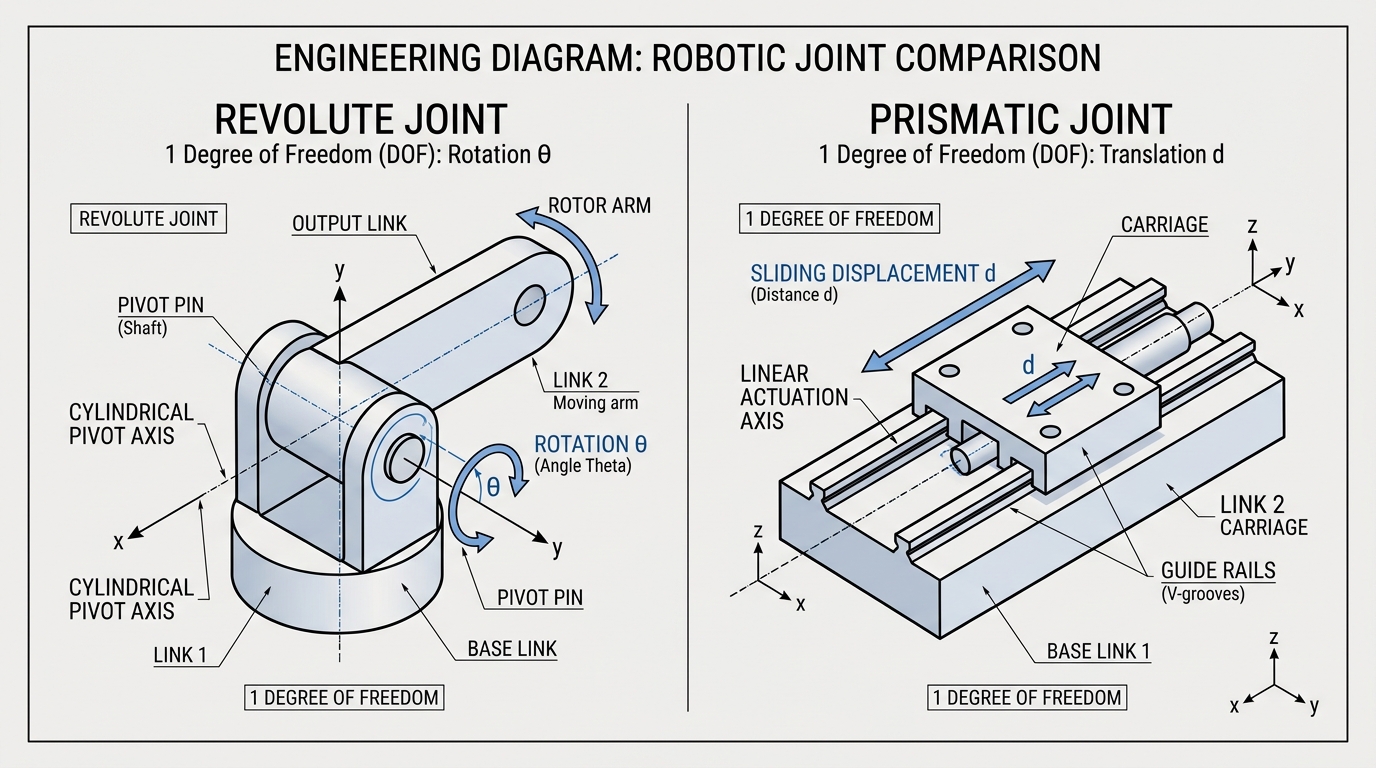
Figure B.5 The two fundamental joint types in robotics. Left: A revolute joint providing single-axis angular rotation (). Right: A prismatic joint providing linear translation () along guide rails.
- Revolute Joint (
/ˈrɛv.ə.luːt dʒɔɪnt/, Noun): A rotary hinge joint that allows motion in only one rotational degree of freedom around a fixed axis (like a door hinge, a knee, or a bicycle wheel). All 6 joints of the UR5e arm are revolute joints. - Prismatic Joint (
/prɪzˈmæt.ɪk dʒɔɪnt/, Noun): A linear slider joint that permits straight-line translation along an axis without any rotation (like an elevator car on rails, a hydraulic piston, or a sliding drawer). The UR5e arm has no prismatic joints, but the fingers of the RG6 gripper slide prismatically along internal tracks to open and close. - Note for Non-Native English Speakers:
- Revolute comes from "revolution" (turning around an axis).
- Prismatic comes from "prism" (straight parallel sides); it does not mean optical glass that splits light into a rainbow, but rather straight-line geometric extrusion.
B.3 Quick-Reference Index of Mathematical & Physical Terms
| Term | Plain English Meaning | Context in This Manipulation Cell | Common Confusion / Pitfall |
|---|---|---|---|
| Target Reticle | An aiming crosshair or visual target marker marking an exact 3D point. | In Figure 2.6, the glowing crosshair locked at the target cube pose where all 8 IK branches meet. | Not a physical robot part; it is a visual UI marker showing the Cartesian target. |
| Discontinuity | An abrupt, sudden jump or break in an otherwise smooth trajectory. | When an IK solver switches branches mid-flight, joint angles jump instantly by hundreds of degrees (). | A physical motor cannot teleport; commands with large discontinuities trigger high-acceleration safety trips. |
| Bimodality (Multimodal) | Having two or more distinct valid solutions or peaks in probability. | Both elbow-up and elbow-down poses reach the cube. A neural network that averages them will predict a broken pose in the middle. | "Mode" in statistics means the most likely value. Bimodal means there are two distinct good answers, not one average. |
| Contact Manifold | The exact geometric patch or area where two physical surfaces press together. | The contact boundary between the rubber gripper pads and the cube faces calculated by MuJoCo 500 times per second. | "Manifold" sounds abstract, but here it simply means the shape of the surface contact area. |
| Friction Cone | The cone-shaped boundary of force within which friction prevents slipping. | Gripper pads must pinch with enough normal force () so that gravity's downward shear force () stays inside the cone ($ | f_T |
| Viscous Damping | Friction resistance proportional to speed (like moving through thick honey), bringing motion to rest. | Prevents simulated arm links from swinging indefinitely like a pendulum when motor power is switched off. | "Viscous" means thick fluid; "damping" means absorbing vibration and kinetic energy (not making something wet). |
| Proprioception | An organism's or machine's internal sense of its own body posture and movement. | High-resolution optical encoders on the motor shafts tell the robot its joint angles () without looking through cameras. | Humans have proprioception when they touch their nose with eyes closed. In robots, it is joint encoder feedback. |
| Plunge & Whip | Action verbs for rapid, dangerous robot motions: plunge (dive steeply downward) and whip (swing violently sideways). | In Figure 2.6, the elbow plunges 48 mm below the tabletop, while the forearm whips across the cell during a shoulder flip. | Engineering hazards caused by selecting incorrect inverse kinematic branches. |